业余无线电 A 类操作证备考 — 2025 新版题库速通
2025 年 10 月起,业余无线电 A 类操作证启用新版题库,从原来的 365 题增至 683 题,考试也从 30 题变成 40 题(32 单选 + 8 多选)。本文基于完整题库分析,整理出易错点、数字速记卡和配套学习资源,帮助你在碎片时间里高效备考。

2025 年 10 月起,业余无线电 A 类操作证启用新版题库,从原来的 365 题增至 683 题,考试也从 30 题变成 40 题(32 单选 + 8 多选)。本文基于完整题库分析,整理出易错点、数字速记卡和配套学习资源,帮助你在碎片时间里高效备考。
Intel HEX文件格式是一种用于表示二进制数据的ASCII文本格式,广泛应用于嵌入式系统的固件存储和传输。
Intel HEX文件格式是一种将二进制数据转换为ASCII文本的格式,适用于8位、16位和32位微处理器。它的主要优点是可以将二进制数据存储在非二进制介质(如纸带、穿孔卡片)上,并且可以通过CRT终端或行式打印机显示。
00111111(十六进制3F)被表示为ASCII字符'3'和'F'。在嵌入式系统中,并发模式通过管理多个任务的并行执行,提高系统的响应速度和资源利用率。本文将详细讲解几种常见的并发模式,并结合实例深入分析,帮助读者深入理解这些模式在嵌入式系统中的应用。
并发模式主要关注如何管理多个任务的并行执行,旨在提高系统的响应速度和资源利用率。常见的并发模式包括:
这些模式通过不同的方式组织任务的并行执行,解决了嵌入式系统中常见的资源竞争、任务调度等问题。
在嵌入式系统中,状态机模式是一种常用的设计模式,通过定义系统的不同状态及其转换规则,帮助开发者更好地管理系统的行为和状态变化。本文将详细讲解状态机模式,并结合实例深入分析,帮助读者深入理解这一模式在嵌入式系统中的应用。
状态机模式(State Machine Pattern)是一种行为型设计模式,它允许对象在其内部状态改变时改变其行为。状态机模式通过将状态封装为独立的类,使得对象在不同状态下可以表现出不同的行为。
在嵌入式系统中,状态机模式可以用于以下场景:
在嵌入式软件开发中,行为型模式通过定义对象之间的通信方式和职责分配,帮助开发者更好地管理复杂的控制流和对象交互。本文将详细讲解几种常见的行为型模式,并结合实例深入分析,帮助读者深入理解这些模式在嵌入式软件开发中的应用。
行为型模式主要关注对象之间的通信和职责分配,旨在提高系统的灵活性和可维护性。常见的行为型模式包括:
这些模式通过不同的方式组织对象之间的交互,解决了嵌入式系统中常见的控制流复杂、代码耦合度高等问题。
在嵌入式软件开发中,设计模式的应用可以极大地提高代码的可维护性、可扩展性和复用性。本文将讲解原型模式和建造者模式在嵌入式软件开发中的应用,并结合实例进行分析。
原型模式是一种创建型设计模式,它通过复制现有对象来创建新对象,而不是通过实例化类来创建对象。原型模式适用于创建对象成本较高或复杂的场景,通过复制现有对象可以提高效率。
在嵌入式软件开发中,原型模式可以用于以下场景:
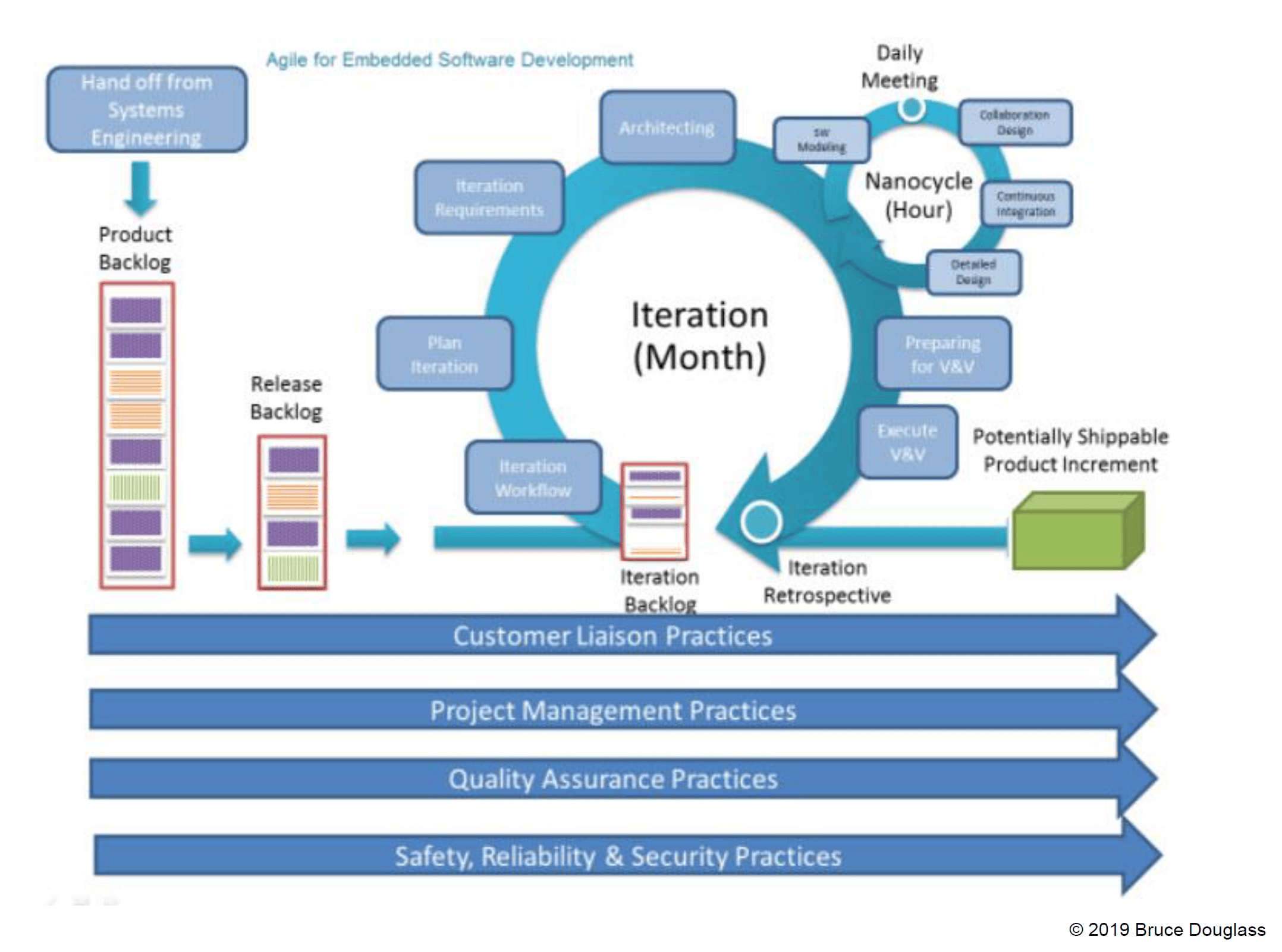
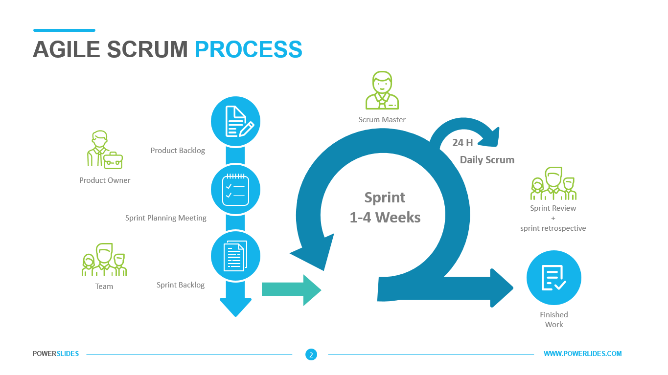
传统的嵌入式软件开发常常面临诸多挑战,例如:客户需求变化频繁、开发周期漫长、软硬件集成困难、测试验证复杂等。传统的瀑布式开发模型在面对这些挑战时显得力不从心。而敏捷开发作为一种迭代、增量式的软件开发方法,以其快速响应变化、提高开发效率和产品质量的优势,逐渐受到嵌入式软件开发领域的关注。本文将深入探讨敏捷方法如何在嵌入式软件开发中落地生根,并分析其优势、挑战以及相应的解决方案。
敏捷开发的核心是敏捷宣言中提出的四大价值观和十二项原则。其中,与嵌入式开发密切相关的实践包括:
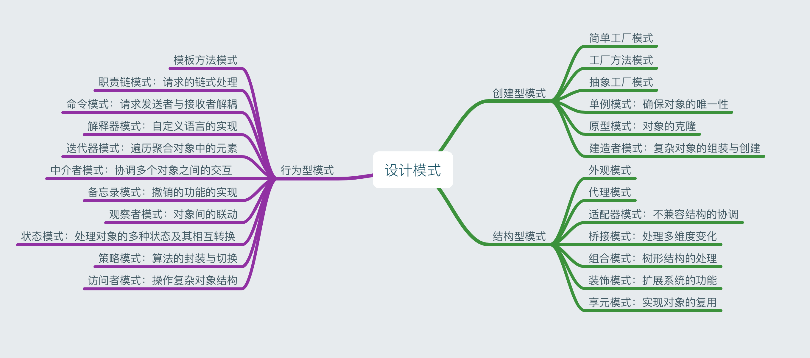
在嵌入式软件设计中,结构型模式扮演着至关重要的角色,它主要描述的是如何将类或对象按特定的布局组成更大的结构,以此来满足复杂的软件设计需求。简单来说,就是如同搭建积木一般,把不同的类或者对象当作积木块,按照一定的规则和方式组合在一起,构建出功能更强大、结构更完善的软件架构。
这些模式可以帮助开发者更好地组织代码,提高软件的可维护性、可扩展性以及复用性。例如,当软件系统规模不断扩大,功能日益复杂时,合理运用结构型模式能够清晰地划分各个模块,明确它们之间的关系,避免代码变得混乱不堪,使得整个软件项目更易于理解、修改和升级,所以它是嵌入式软件设计里不可或缺的设计思路和方法。
结构型模式通常可以分为类结构型模式和对象结构型模式这两大类。
类结构型模式主要依靠继承机制来组织接口和类,通过创建类之间的继承关系,子类可以继承父类的属性和方法,并且可以根据自身需求进行扩展或重写,进而构建出更大的系统结构。不过,继承关系往往会带来较高的耦合度,因为子类与父类紧密相连,父类的改变可能会影响到子类,使得代码的灵活性和可维护性在一定程度上受到限制。
而对象结构型模式则采用组合或聚合的方式来组合对象。组合是指将对象组合成树形结构,体现部分与整体的层次关系,整体对象可以控制部分对象的生命周期等;聚合则是一种相对松散的关系,部分对象可以独立于整体对象存在,整体对象只是对部分对象进行引用和使用。这种通过关联关系来组合对象的方式,相较于继承关系而言耦合度更低,符合 “合成复用原则”,能够让软件系统在应对需求变化时更加灵活,方便进行功能的扩展和调整,大部分常见的结构型模式都属于对象结构型模式。
在嵌入式软件开发中,单例模式是一种非常常见的设计模式,用于确保某个类在系统中只有一个实例,并提供一个全局访问点。这种模式在资源受限的环境中尤为重要,因为它可以避免资源的重复分配和浪费。本文将结合具体实例,深入讲解和分析单例模式在嵌入式系统中的应用。
在嵌入式系统中,单例模式广泛应用于资源管理、配置管理和通信管理等场景。通过单例模式,可以确保系统中只有一个实例来管理共享资源,避免资源冲突和配置不一致的问题。以下是单例模式在嵌入式系统中的主要优势: